The picture below is a Colonial tip knife from the 1940s.
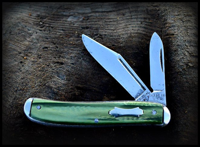
Many company’s made tip knives but Colonial held the patent.
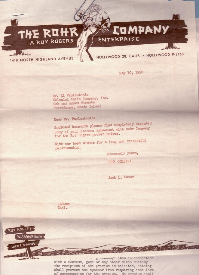
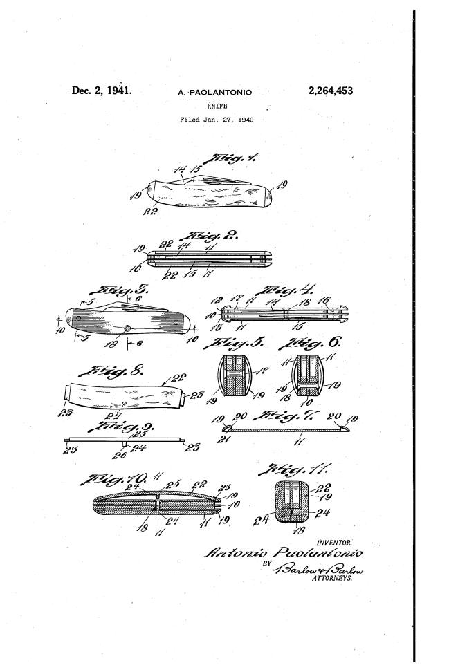
Patented by Antonio Paolantonio. U.S. Patent # 2,264,453
This patent was filed for on January 27, 1940 and approved on December 2, 1941.
I believe Colonial made and sold tip knives for many years before applying for the patent.
I have tip knives made by Colonial with curved tang stamps that are known to be made between 1926 and 1938.
A tip knife has no solid bolsters at each end like a lot of knives at the time. There were small hollow bolsters connected to each end of the metal plates in the body of the knife. The skeleton of the knife could be assembled and stored and a celluloid handle attached later when ordered.
So basically Colonial said the benefits of this knife were ease of assembly, stronger than other knives of its type and it looked better to hide the rivets in this way.
Here is exactly how they said that.
“This invention has for one of its objects to provide a more rugged and stronger hinged mounting of the knife blade than heretofore provided in a knife of this character.”
“Another object of the invention is to conceal the rivets which are usually provided for holding the cover upon a knife.”
“Another object of the invention is to provide an arrangement whereby the cover sections will be assembled after the metallic portion of the knife is all assembled in relation so that the main body portion of the knife may be made up ahead of time and then covers assembled on the body portion of the knife in accordance with the choice of the customer to whom they were furnished.”
“Another object of the invention is to conceal the rivets which are usually provided for holding the cover upon a knife.The rivets are somewhat unsightly, especially as they sharply contrast with the color of the cover section”
Below I will be adding the original patent and Antonio Paolantonio’s description and drawings of his invention.I will also add pictures of Colonial tip knives from my collection.
There are many typos, misspelled words and other weird things like funny old words included in the original patent. I edited some that were confusing while leaving the ones that weren’t as bad because I think it is interesting.
This is from the original patent.
Filed Jan. 27, 1940
Patented Dec. 2, 1941 For Antonio Paolantonio, Johnston, R. I., assignor to Colonial Knife Company, Inc., a corporation of Rhode Island 11 Claims.
This invention relates to a knife of the character often referred to as a tip knife; that is, one in which there are no bolsters at the ends of a size adapted
to receive rivets therethrough; and this invention has for one of its objects to provide a more rugged and stronger hinged mounting of the knife blade than
heretofore provided in a knife of this character.
Another object of the invention is to conceal the rivets which are usually provided for holding the cover upon a knife.
A further object of the invention is to provide a knife in which the cover sections may be held against separating from the metallic plate or scale portions
over which they extend.
Another object of the invention is to provide an arrangement whereby the cover sections will be assembled after the metallic portion of the knife is all
assembled in relation so that the main body portion of the knife may be made up ahead of time and then covers assembled on the body portion of the knife in
accordance with the choice of the customer to whom they were furnished.
With these and other objects in view, the invention consists of certain novel features of construction as will be more fully described and particularly pointed
out in the appended claims.
In the accompanying drawing:
Fig. l is an elevation of the knife completed;
Fig. 2 is a top plan view thereof; v
Fig. 3 is an elevation of the body portion of the knife with the cover removed;
Fig. 4 is a top plan View thereof;
Fig. 5 is a section on line 5 5 of Fig. 3;
Fig. 6 is a section on line 6-6 of Fig. 3;
Fig. ‘7 is a sectional View through one of the plates or scale portions of the knife; n
Fig. 8 is an elevation of one of the cover sections;
Fig. cover;
Fig. is a sectional View on substantially line Ill-l0 of Fig. 3, illustrating one of the cover sections
assembled and another of the cover sections in one of the positions which it assumes in being moved to
assembled position;
Fig. 1l is a sectional view on line II-II of Fig. 10.
Folding knives of the so-called tip type in which there are no bolsters of a size to receive rivets there
through usually have the rivets extending through the covers which extend along the scale or outer plates of the
knife body whereby the rivets hold the knife body as well as a cover in assembled relation. The covers are usually of Celluloid or
some non-metallic material which is rather soft and the rivet heads which engage these softer cover portions will permit of some relative
movement of the assembled parts if some pressure is brought to bear upon the knife blade which is pivoted upon the end rivets of such assembly.
Further,
the rivets are somewhat unsightly, especially as they sharply contrast with the color of the cover section; and again,
when knives are formed up in the above-mentioned manner, the covers are a part of the complete assembly and cannot be
easily changed if a different colored cover is desired.
Accordingly, in order to provide a stronger construction I have riveted the metal parts of the knife together as a unit body
and have assembled the cover so as to conceal these rivets; the cover being assembled `as a separate operation enables the body
to be made up and the covers assembled as a last operation whereby a large number of bodies maybe made up without covers, and the
covers assembled thereon as a last operation in accordance with the orders for various colors which may be received, thus enabling
a large part of the assembly operations to be performed ahead of time and minimizing the carrying of stock upon manufacturers
shelves.
I further provide for the better holding of the cover in position by welding the opposite covers together against the metallic
scales of the knife; and the following is a more detailed description of the present embodiment of the invention, illustrating the
preferred means by which these advantageous results may be accomplished:
With reference to the drawing, Ill designates a center plate and II, outer plates or scales spaced ,from the center plate Il] by
spacers I2 and I3. These spacers also serve as resilient or spring portions for assisting in holding the knife blades I4 and VI5 in different adjusted positions.
The knife blades I 4 and I5 are pivoted upon a rivet I6 which extends through the plates and blades to hingedly mount the blades
between the plates and also engages the end of each blade so as to hold the bladein either closed or open position in a usual manner.
The rivet Il extends through the plates and spacer at the opposite end of the knife and is headed over the metallic plates so as to hold them firmly in assembled relation. kThe hollow rivet also extends through the plates and spacer atsuboutwardly to open
position, even though there is considerable lateral stress brought to bear upon v the blade, the portions which embrace the pivot rivet
i6 are well supported against spreading by the blades by reason of such pressure.
This unit assembly so far described may be made up ahead of time or in quantities, leaving the cover sections which are now to be described
to be later assembled.
Each of the scales or plates ii consists of a sheet of stock in which the tip ends i9 are split and raised as at 2G so as to provide openings
2i beneath these tip portions. The cover, riesig nated generally 22, shown in Fig. 8, is formed of non-metallic material such, for instance, as
Celluloid, although any moldable material which is somewhat flexible may be provided.This cover section is molded with fingers 23 at either end
and a projecting portion 24 at its middle point which will be in such position that it may extend into the hollow rivet i8 above referred to.
These cover sections will be of Various colors and will be assembled onto the body of the knife in the color ordered by iiexing to draw the fingers 23 at the
ends toward each other a distance sufiiicient to project them into the slots 2i in the scale and beneath the tips and then releasing to permit these sections
to move back into a straightened position and by such straightening cause the fingers 23 to extend beneathf heat the knife at this location so that
a welding v of the ends 26 of the projections li may occur, or I may so moisten the end portions of the projections 24 with a solvent that they will become
softened and upon pressure forcing these two tips together, they will become welded for effectively becoming a single piece extending through the rivet i8. One such
solvent which may be used for Celluloid is acetone.
In this manner, when the portions 24 become dried and hardened, the two cover sections will be held against movement apart or separation, and
not withstanding changes
in temperature which often affect Celluloid, the cover sections will be held firmly against the scales or plates Il and against separation or release
therefrom, While at the same time covering the rivets making a more sightly appearance and enabling the rivets to engage the metal surfaces to better hold
the parts against stresses which may occur.
The foregoing description is directed solely towards the construction illustrated, but I desire it to be understood that I reserve the privilege of resorting to all
the mechanical changes to which the device is susceptible.
I claim:
1. In a tip knife, a plurality of metal plates, a spacer between said plates, rivets extending through said plates and headed over in contact with said plates, a
non-metallic cover over said rivets hiding the same from View, means to secure said cover in said assembled position, one of said rivets being hollow, and said
cover being provided with a non-metallic projection extending well into said hollow rivet.
2. In a tip knife a plurality of metal plates, a spacer between said plates, rivets extending through said plates and headed over in contact with said plates, non-metallic covers over said rivets hiding the same from View, means to secure said covers in said assembled position, one of said rivets being hollow, and means extending through said hollow rivet from opposite sides thereof to lock the covers together against outward movement.
3. In a tip knife, a plurality of metal plates, a spacer between said plates, rivets extending through said plates and headed over in contact with said plates, non-metallic covers over said rivets hiding the same from view, means to secure said cover in said assembled position, one of said rivets being hollow, said covers being each provided with
a projection to extend into said hollow rivet from opposite sides thereof and said projections being secured together.
4. The method of securing a non-metallic cover on a knife which consists in molding the cover in side sections with a projection on each section and welding said projections
together through the knife to hold the opposite sections on each side of the knife.
5. In a tip knife, a pair of outer metal plates, a spacer between said plates, rivets extending through said plates and headed over in contact with said plates to provide a unitary assembly,
and non-metallic covers on opposite sides of said riveted assembly over said rivets hiding the same from View, said covers being integrally connected to each other by non-metallic material extending through said riveted assembly.
6. In a tip knife, a pair of outer metal plates, a spacer between said plates, rivets extending through said plates and headed over in contact with said plates to provide a unitary assembly, non-metallic covers on opposite sides of said riveted assembly over said rivets hiding the same from view, and means carried by eachplate to secure one of said covers in assembled relation thereto, said covers being integrally connected to each other by non-metallic material extending through said riveted assembly.
‘7. In a tip knife, a pair of outer metal plates each having each end portion thereof provided with a hollow integral outer tip with an opening
extending thereinto, rivets securing said f plates in assembled relation, and a cover over said rivets and having end projections formed of the stock of the cover extending through said openings into said tips to assist in holding the cover over said plate.
8. In a tip knife, a pair of outer metal plates, each having each end portion thereof provided with a hollow integral outer tip with an opening extending thereinto, rivets securing said plates in assembled relation, a cover over said rivets with the ends thereof extending through said opening into said tips to assist in holding the cover over said plate, one of said rivets being hollow, and said cover being provided with a projection formed of the same material as the cover and extending into said hollow rivet.
9. In a tip knife, a pair of outer metal plates, each having each end portion thereof provided with a hollow integral outer tip with an opening extending
thereinto, rivets securing said plates in assembled relation, a cover over said rivets with the ends thereof extending through said opening into said tips
to assist in holding the cover over said plates, one of said rivets being hollow, and non-metallic means extending wholly through said hollow rivet and fast to
each cover to lock the covers together against outward movement.
10. In a tip knife, a pair of outer metal plates, each having each end portion provided with a hollow integral outer tip with an opening extending there into, rivets securing said plates in assembled relation, cover sections over said rivets and extending through said openings into said tip portions to assist in holding the covers over said plates, one of said rivets being hollow, said covers being provided with projections to extend into said hollow rivet from opposite sides thereof and said projections being secured together.
11. The method of forming a backing plate for a tip knife which consists of providing a metal iblank, splitting the stock adjacent the ends thereof and raising the portions of the plate extending from the splits to the end extremity of the plate to form a pair of hollow integral outer tips.
ANTONIO PAOLANTONIO.
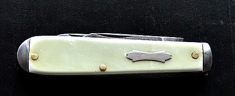
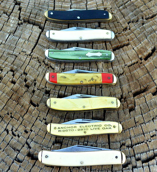
These are pictures of some of my Colonial tip knives.
This is an old one made between 1926 and 1938.
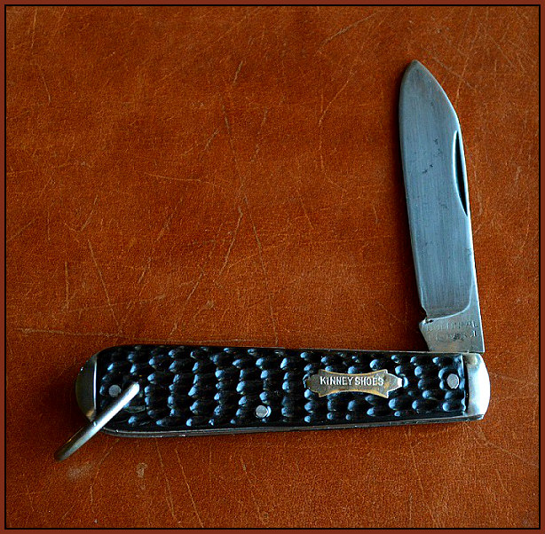
A Kinney shoes tip knife from the 1950s.
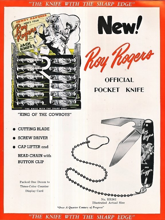
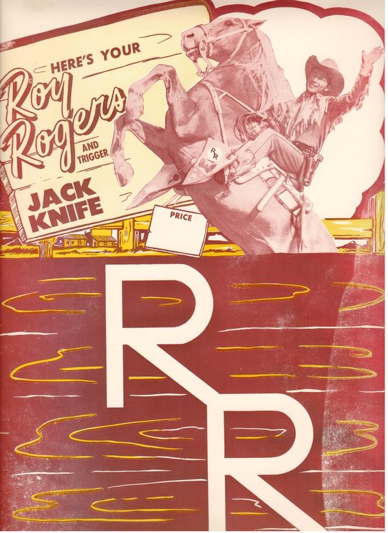
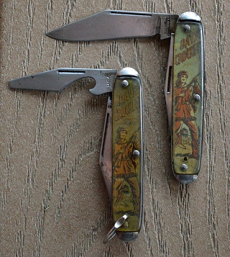
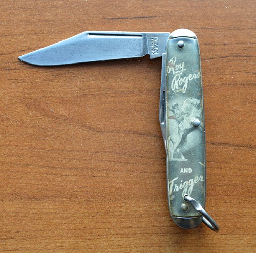
The Model 826 by Colonial was also a tip knife. This was a very popular knife due to all its use for the novelty character knives like Roy Rogers, Davy Crockett and many others.
More Colonial tip knives.
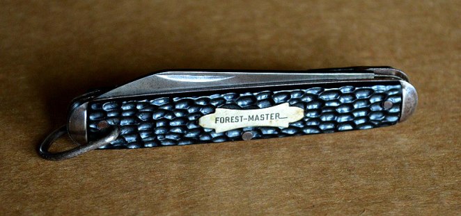
Even this old Forest Master made between 1926 and 1938 is a tip knife.